Furnace
A ~$100 tube furnace that reaches over 1,000 °C and can be assembled in two hours if you know what you’re doing.
Ingredients
- MMasters ceramic fiber insulation blanket (24 x 8 x 1 in) (Amazon)
- Master Wire Supply Kanthal A1 wire (22 gauge, 50 ft) (Amazon)
- beinkmake insulating ceramic support rods (7.87 x 0.08 in, 10-pack) (Amazon)
- CDMALL AC motor speed controller (120 V, 15 A) (Amazon)
- GTJ silicone baking mat roll (12 in x 6 ft) (Amazon)
- Quartz glass tube (1 in OD, 0.866 in ID, 12 in long) (McMaster-Carr)
- Ceramic washers (1.062 in ID, 2.5 in OD) — 2 required (McMaster-Carr)
- K-type kiln thermocouple probe (0–1300 °C, 3.3 ft extension wire) (Amazon)
- HBN plug-in watt meter with backlight (Amazon)
- Proster dual-channel thermocouple thermometer with 2 probes (Amazon) or SafeSense TempTouch Wi-Fi thermocouple sensor (Amazon)
- High-temperature polyimide tape (1 in x 33 m) (Amazon)
- GUBCUB two-way ceramic terminal blocks (25 A, 380 V, 5-pack) (Amazon)
Steps
V = IR
W = IV
360 W = 120 V × 3 A
120 V = 3 A × 40 Ω
-
Measure and cut the wire
Measure and cut a ~40-ohm length of Kanthal A1 wire. Remember to err shorter rather than longer, because you can compensate with the AC motor speed controller. If you cut too long, such that you can’t get enough power using the 120 V wall outlet, then your furnace might not get hot enough. Shorter is also easier for winding. If you cut way too short you will not have good control over the system.
-
Wind the heating element
The next steps require some finesse. Find something approximately the thickness of a pencil, but ideally round, more rigid, and slightly longer—something like a threaded rod or dowel.
Uniformly wind the wire around that rod until it is the desired length for your heating element (~6 inches if you are using the 8-inch-wide insulation listed above). Once you’ve wound 6 inches, slide the winding off the rod; it should hold its shape.
Start winding another 6 inches with ~2 cm of straight wire between the windings, until you’ve consumed enough of the wire. Make sure to leave ~6 inches of unwound wire on either end to have ample room for electrical connections.
-
Secure the coils to the insulation
Place the ceramic fiber insulation flat onto a working surface. Use gloves and be outdoors or in a safely ventilated setting.
Insert one of the ~6-inch wire leads through the insulation 1 cm in from a corner, pulling the lead through until the first wound coil stops it from moving further. Place one of the ceramic rods through the middle of this first coil so it can’t bend. The rods are there only to provide structural support; the Kanthal A1 wire is the heating element.
Make a switchback pattern with the subsequent coils, ensuring that in total the switchbacks don’t take up more than 7.8 inches of the ceramic fiber insulation (2.5 inches, the outer diameter of the washer, × 3.14).
Insert ceramic rods into each coil, and cut ~2 cm lengths from your original spool of wire to use as staples to secure the coils into the insulation. Be careful to ensure coils and staples aren’t at risk of shorting to each other.
Once all the coils are safely secured, thread the ending lead through the ceramic fiber insulation and pull it taut, like you did at the beginning.
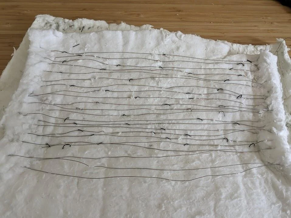
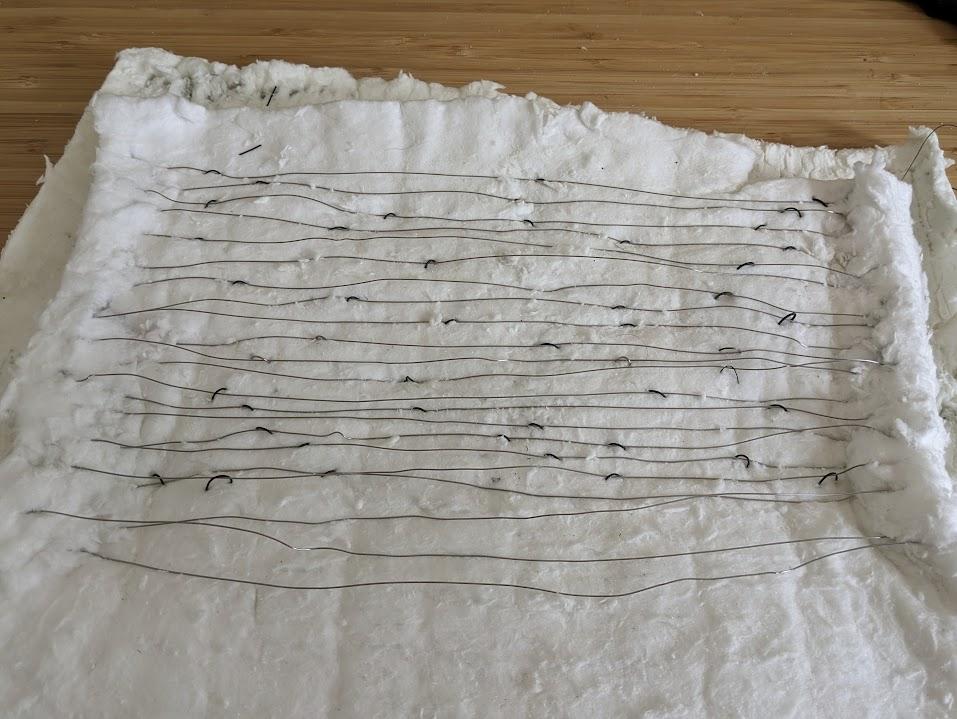
This image is from an older furnace iteration. It does not have the described coils with rods in the center, but it does show the switchbacks secured by metal staples. Hopefully it gives you a sense of how things might look. Sorry for not having an up-to-date photo of this step. View full-size photo A diagram is coming soon to better explain this.
-
Position the quartz tube and washers
Once the coils are secured, place the ceramic washers around the quartz tube. Place the tube centered on the insulation, protruding 2 inches out from it on either side if you bought the insulation above, with each washer on either side of the coils, ~1 cm from the end of the insulation.
-
Roll the insulation
Roll the insulation around the washer/tube system until the insulation totally surrounds it, then continue rolling until you run out of insulation. Keep threading the leads through the insulation so they have a path out from the center.
Be careful as you roll that the coils stay put. If they get dislodged and close to each other, they may continue to move around and immediately or eventually cause a short. If you notice the coils are too close, unroll the insulation and adjust them, securing with additional staples, changing the coil spacing, or whatever else is necessary to ensure this risk is sufficiently mitigated.
-
Wrap the furnace
Wrap the whole insulated cylinder with the silicone sheet, cutting it to size, and use Kapton tape to prevent unraveling and keep everything together. The leads should puncture the silicone cover so you can connect to them.
-
Connect the electrical leads
Connect the heating element’s electrical leads and the hot and neutral conductors of a modified electrical outlet cable (any old extension cord or power supply cable) using the ceramic electrical terminal.
View full-size photo -
Add end caps
Add silicone or Home Depot tile end caps on either side of the tube for fanciness.
Furnace end caps · 3-second video. View on Google Photos -
Connect power and monitor the temperature
Plug into your AC motor speed controller, power meter, and a wall outlet.
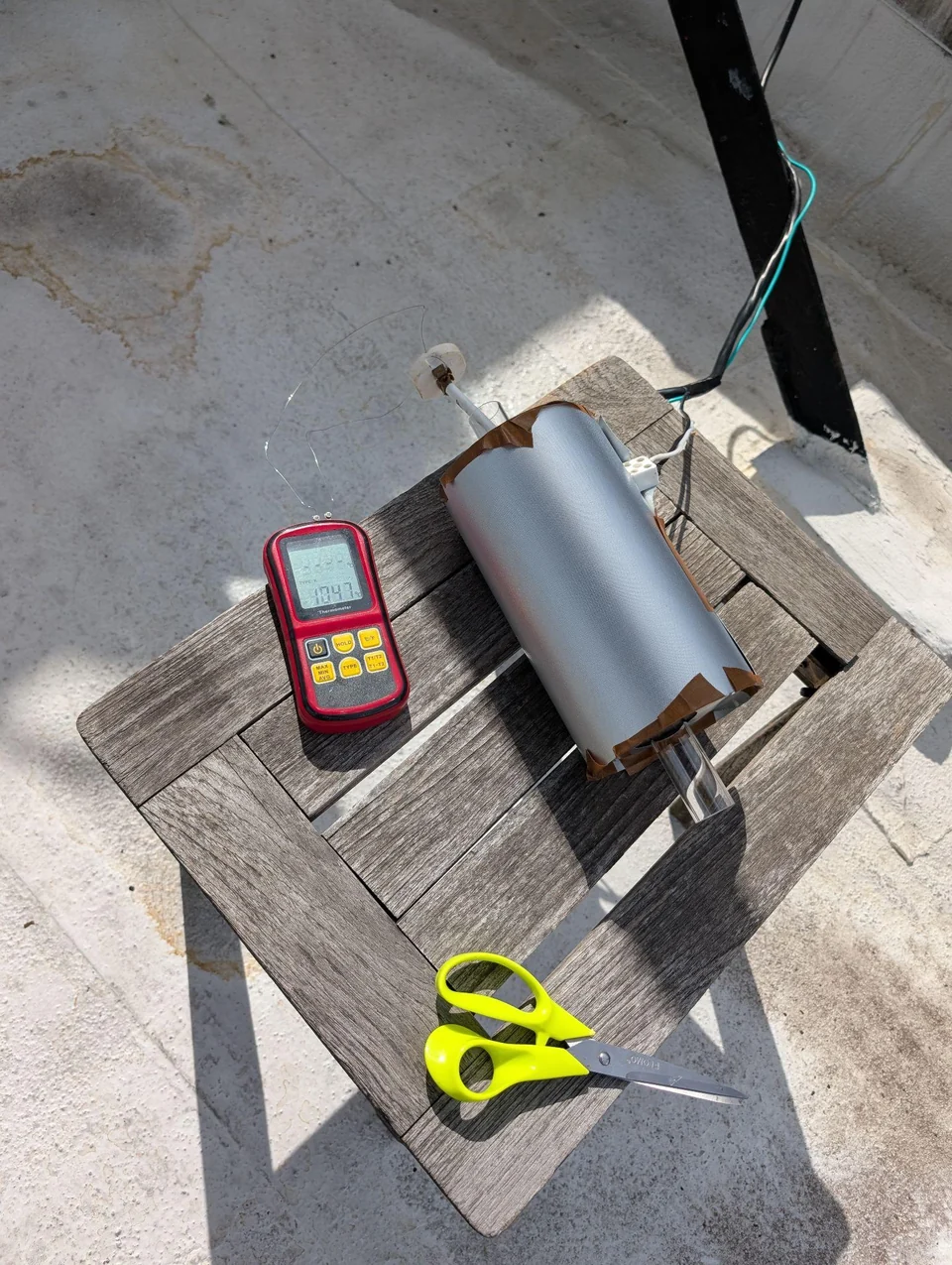
Slowly ramp while monitoring the temperature in the tube.
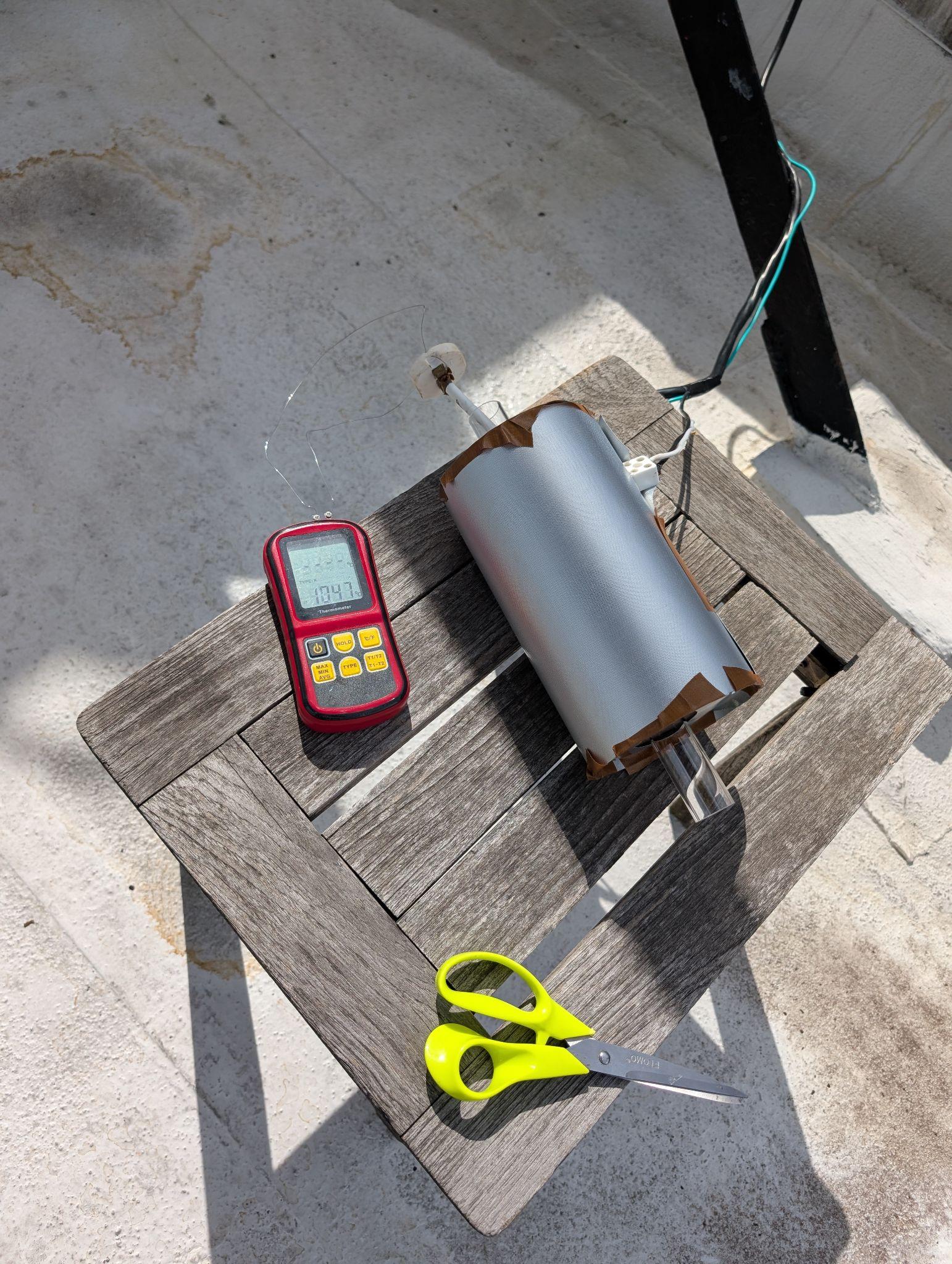
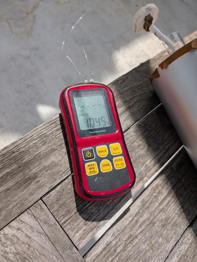
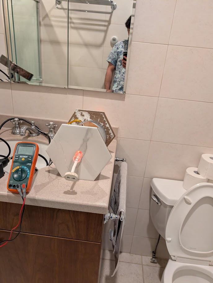
If you built the furnace right, you should be able to swap out tubes fairly easily because they are only touching the ceramic washers. You can be fancy and have a tube for everything: a temperature calibration with the thermocouple in its tube, a dry gate oxidation tube, a P-type doping tube, an N-type doping tube, a wet oxide tube, an anneal tube, etc.
As you make devices, remember that cleanliness is important. During high-temperature steps in particular! There are so many ways a home or cheap chip fab can go wrong. Sensitivity to contaminants during thermal processing is one to pay attention to.
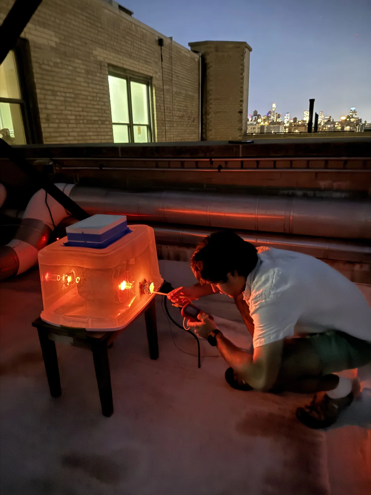
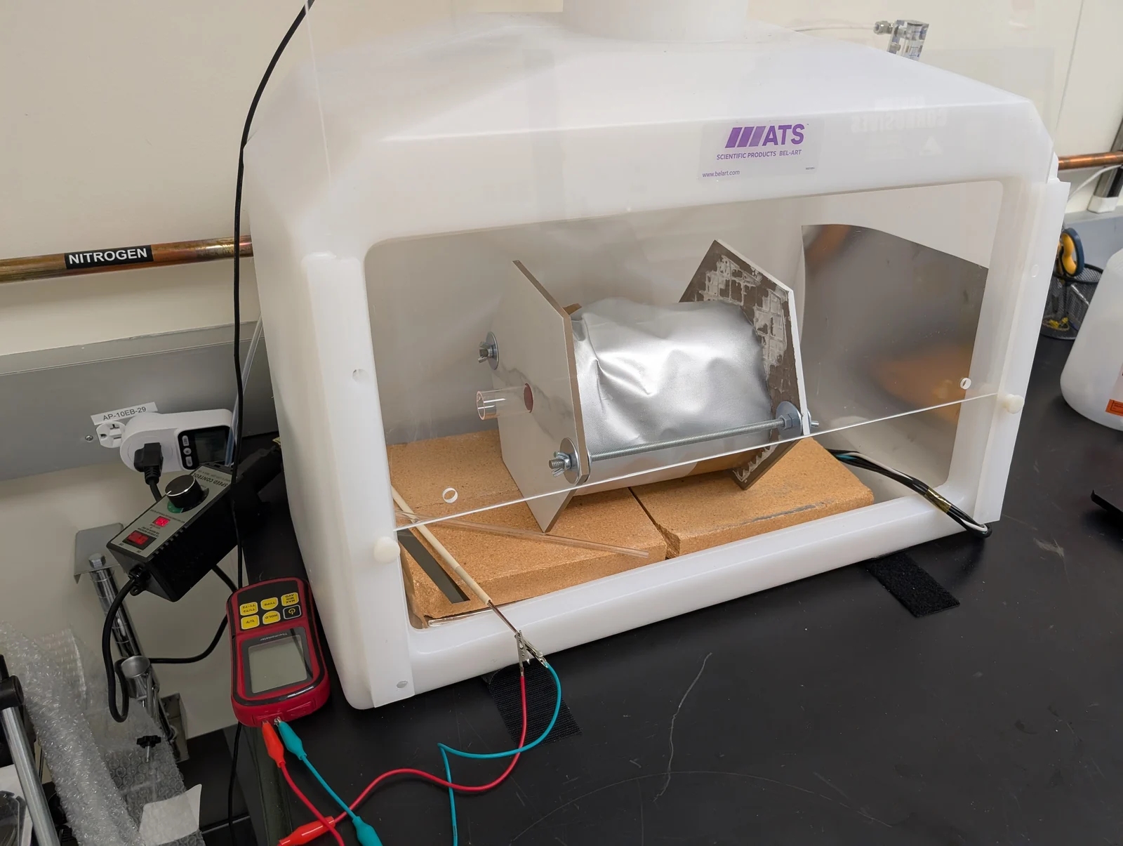
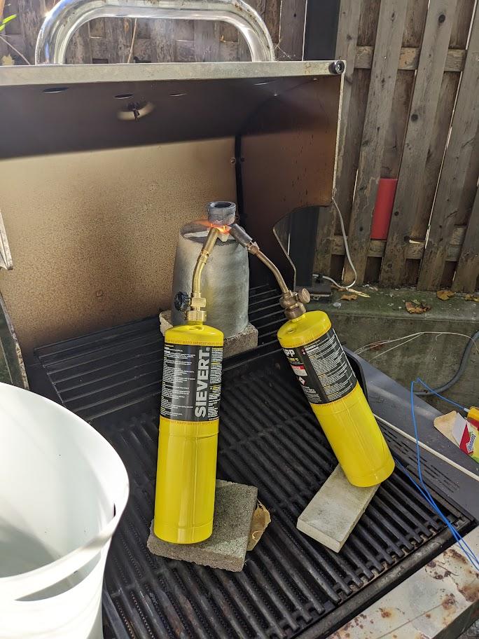
A potentially much easier thing to do than build your own furnace is to just buy the quartz tube from McMaster-Carr and buy a couple of canisters of MAPP welding gas, slowly heating the tube or a region of it to the desired temperature. Be careful not to make it explode from significant temporal or spatial temperature gradients. I haven’t tried this, but I think it would get you hot enough to do some doping.